JavaScriptを有効に設定してからご利用ください。
複雑化する製造現場の課題を、三菱電機の知見とデジタル技術によって解決するサービスが新発売!
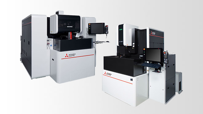
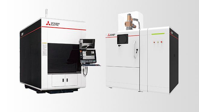
プリント基板製造分野をリードする幅広いソリューションを提供
三菱電機クラウド検針サービスの無償トライアルキャンペーンを実施中!検針業務の効率化を実現するサービスを、ぜひお試しください。
搬送ライン設計・管理担当者のお悩みを解決
(外部サイトへ遷移) 販促コンペで、FAの“難しそう”を“おもしろそう”に変えるアイデアを募集中です!
150名様にギフトが当たる!“FAサイト・FA Web Shop会員登録・更新キャンペーン”実施中
IoTを活用し、生産性向上と付加価値を創出進化したものづくりをご提案するe-F@ctory
もっと見る
お知らせ一覧
カタログ
2024-04-01
マニュアル
技術資料
ソフトウェア
サンプルライブラリ
新製品
生産終了
規格適合品
その他
更新情報一覧
展示会・セミナーの各種イベントや、製品コンセプト・加工動画などの動画をご覧いただけます。
産業分野のオートメーションに関する技術動向や注目テーマ、最新トレンドなどに関して、三菱電機がお届けする産業界向け情報メディアです。
公式SNSアカウントでは、FAに関する最新情報を発信中!