MELSEC MX Controller MX-R Model Selection Screen Operation Instruction
1. SCREEN CONFIGURATION
● Main screen
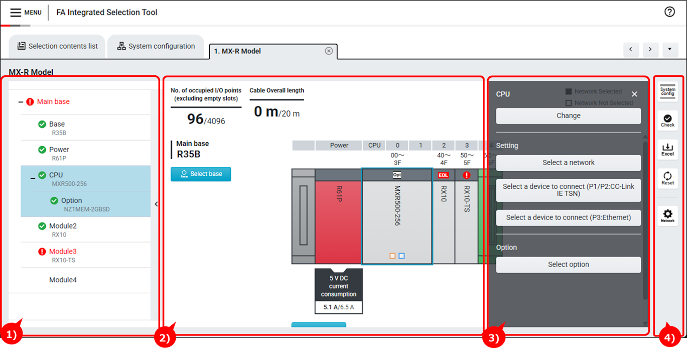
1) List display area
Model names of the selected products are displayed.
| Display item | Description |
|---|---|
 | Click a product to display the drawer menu. |
 | This mark is displayed when a product is faulty. Details can be checked from error check. |
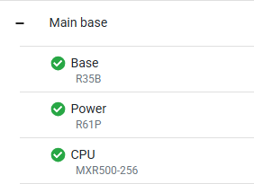
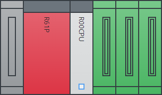
2)Selection result
Image and information of the selected products are displayed.
| Display item | Description |
|---|---|
 | Click a product to display the drawer menu. |
 | This label is displayed for products of which options have been selected. |
 | This label is displayed for products which have been discontinued. |
 | These squares are displayed for products supporting network. The solid square indicates the module is connected to a network. |
 | This mark is displayed when a product is faulty. Details can be checked from error check. |
 | Displays the drawer menu of the selected base. |
 | Displays the screen for selecting an extension base. |
3)Drawer menu
Menu of the selected module is displayed.
| Display item | Description |
|---|---|
 | Menu of the selected module is displayed. Click the menu to perform operation. |
4) Auxiliary button area
Various buttons for checking and resetting selections are displayed.
| Display item | Description |
|---|---|
| Displays the configuration diagram of the selected products. | |
| Performs integrity verification of the selected products. | |
| Outputs selection result as an Excel file. | |
| Discards the selections to restart selection from the beginning. | |
| Configure network connection settings for selected products at one time. |
2.OPERATION PROCEDURE
Step 1:Adding modules
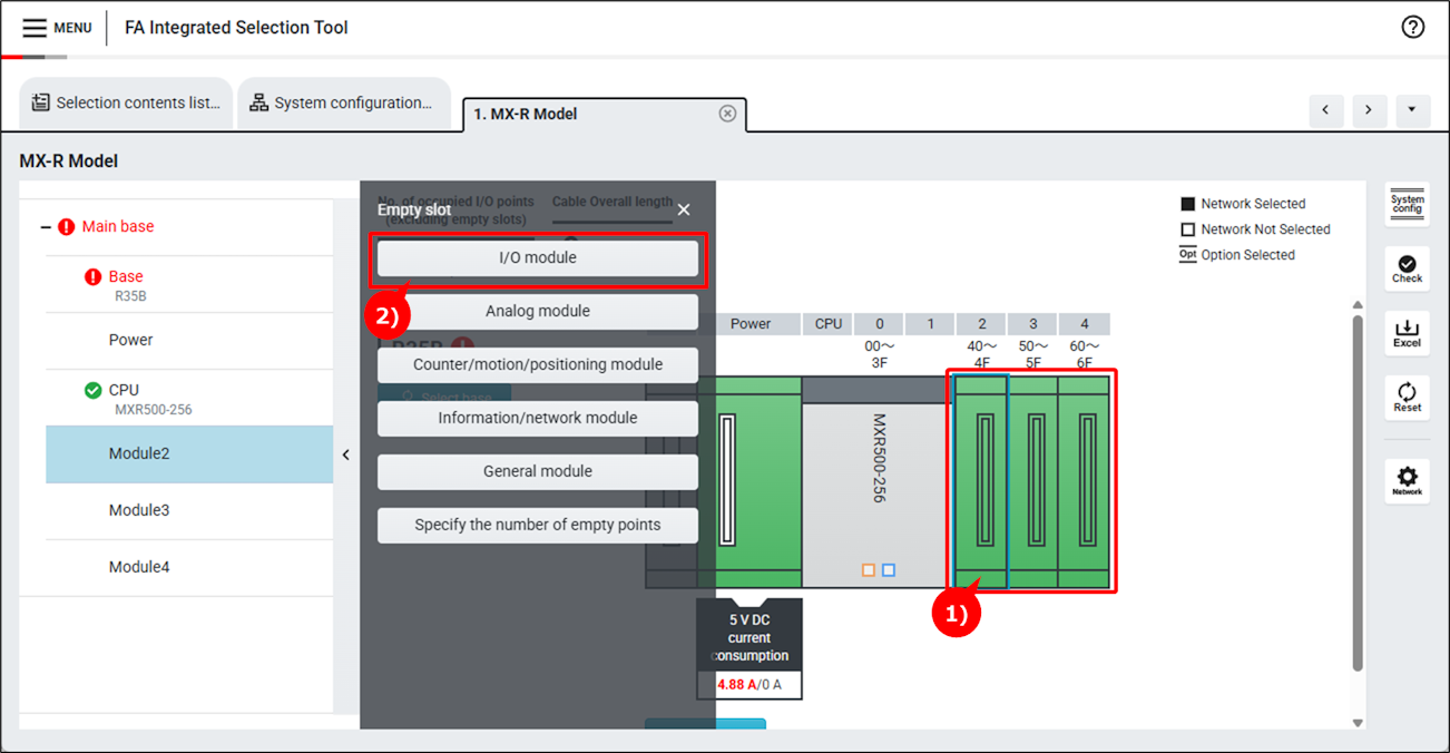
1) Select a slot where modules to be added.
2) Click a module type to be added.
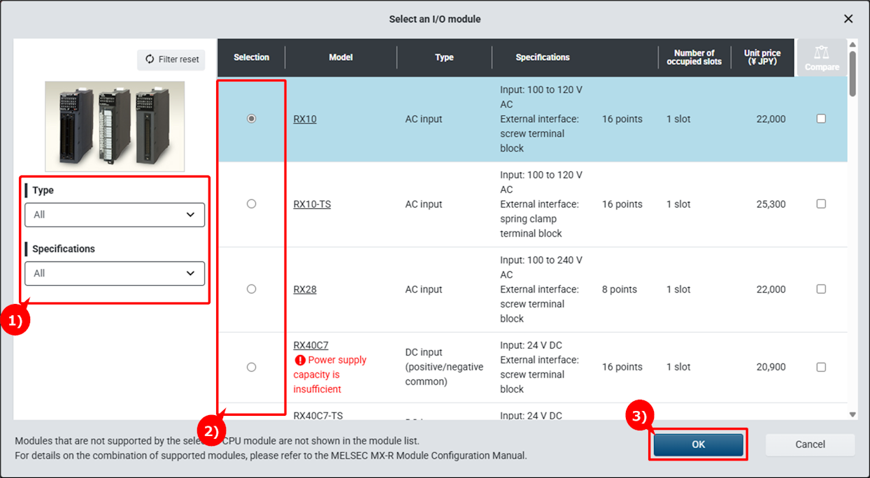
1)Conditions for filtering modules can be specified.
2)Select a module.
If the power supply capacity is insufficient when the module is installed, a warning mark will appear.
3)Click "OK" button.
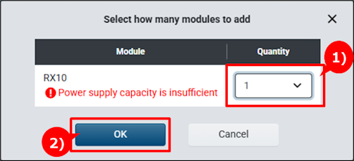
1)Specify the quantity as needed.
If the power supply capacity is insufficient when the specified quantity of modules are installed, a warning mark will appear.
2)Click "OK" button.
3)The selected module is added.
Step 2:Adding an extension base unit
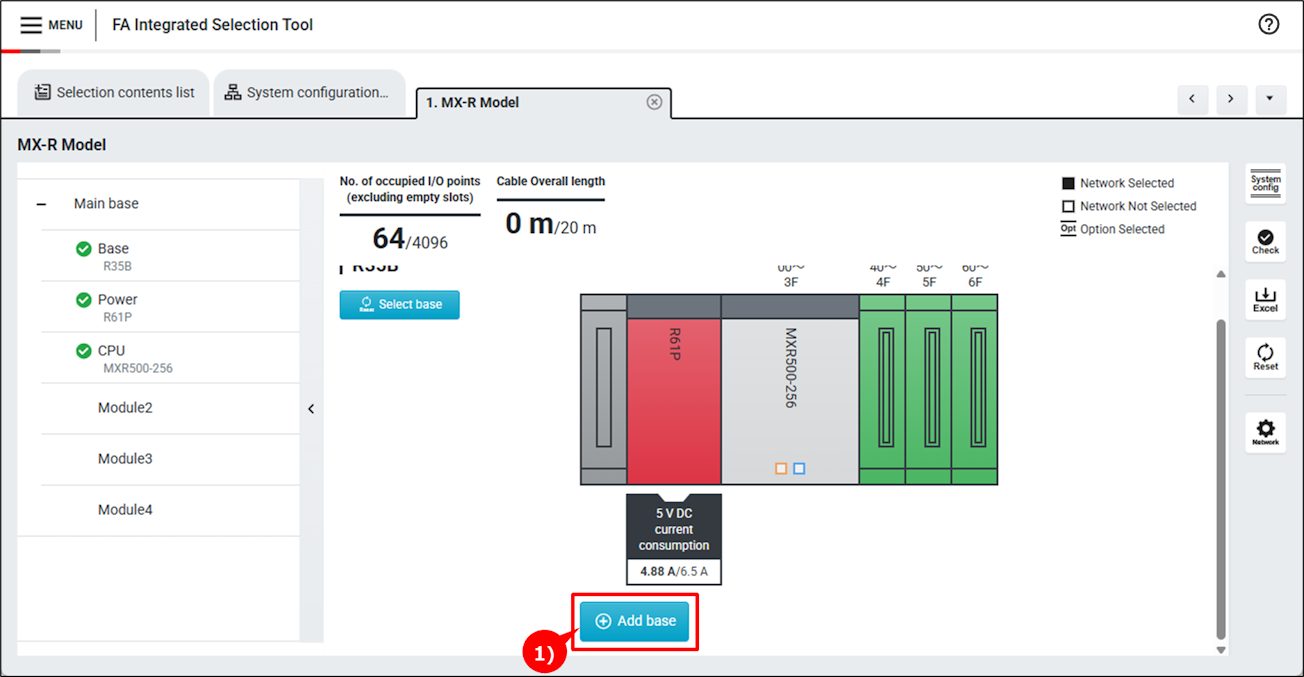
1)Click "Add base" button.
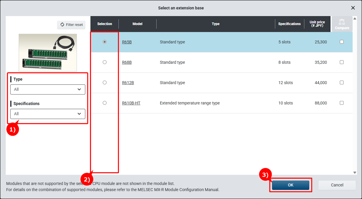
1)Conditions for filtering base units can be specified.
2)Select a base unit.
3)Click "OK".
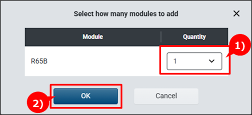
1)Specify the quantity as needed.
2)Click "OK" button.
3)The selected base unit is added.
Step 3:Adding options
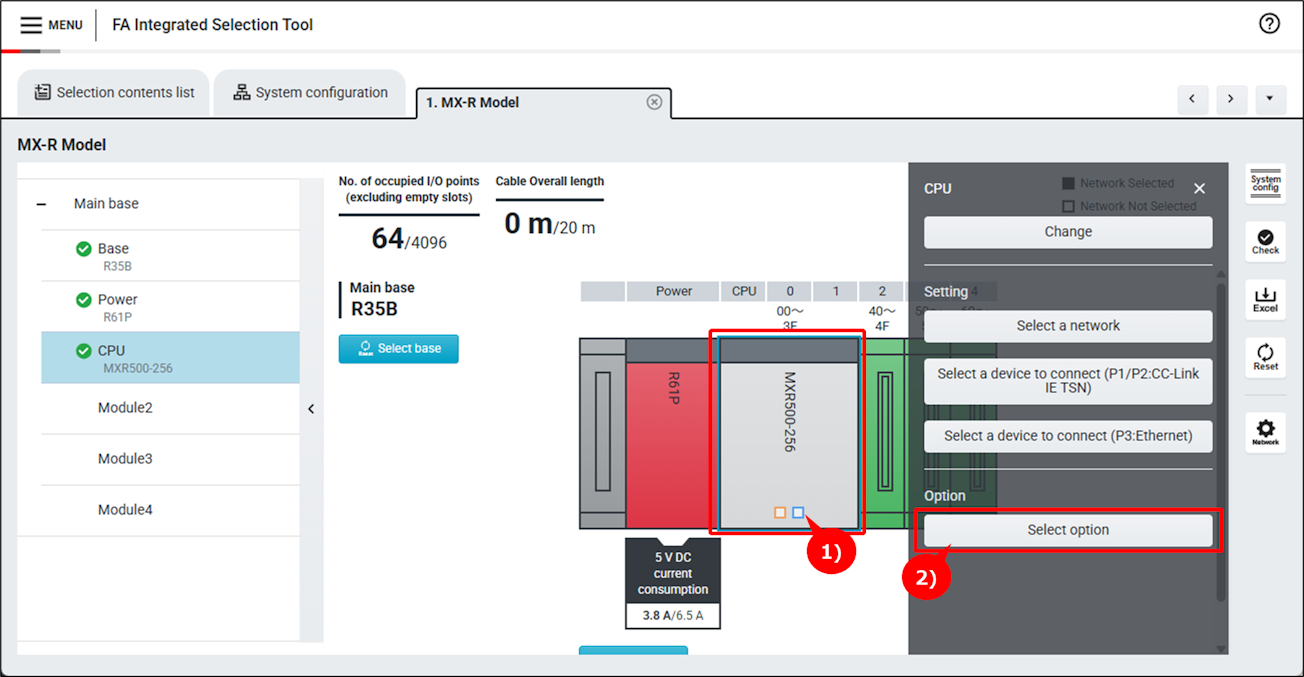
1)Click a module to which options to be added.
2)Click "Select option" button.
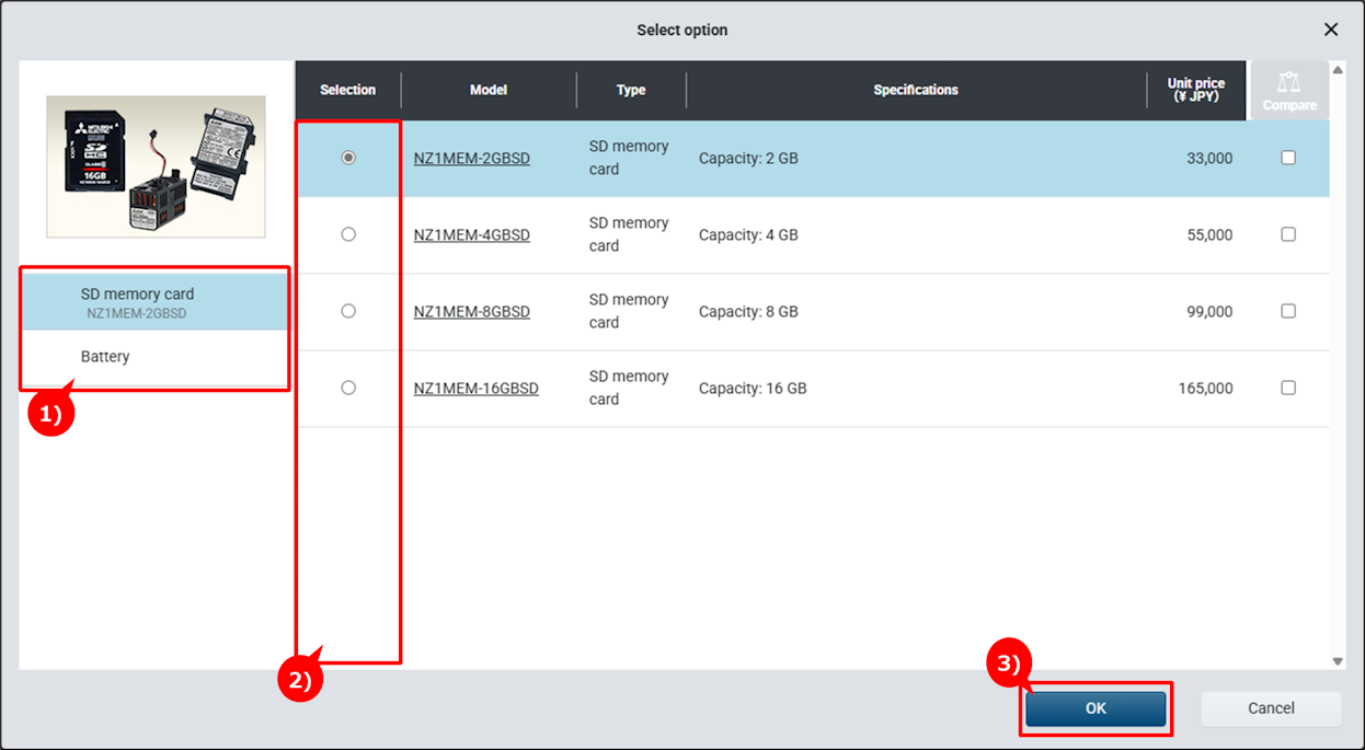
1)Select an option group.
2)Select an option.
3)Click "OK" button.
4)The selected option is added, and "OPT" mark is displayed on the module.
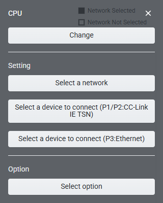
Step 4:Selecting devices to be connected
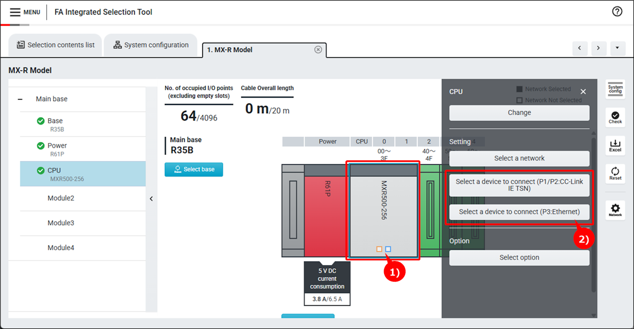
1)Click a module to be connected.
2)Click "Select a device to connect" button.
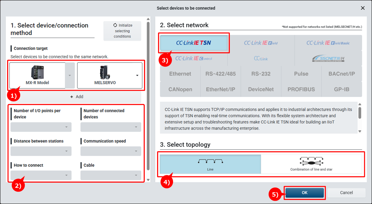
1)Select devices to be connected. Connectable networks are narrowed down according to the selected devices.
2)Target networks can be narrowed down by specifying Filter and Point to select.
3)Select a network.
4)When topology selection is necessary, the topology selection screen will be displayed.
5)Click "OK" button.
6)An icon of the selected device is placed on the system configuration diagram.
Step 5:Selecting a network
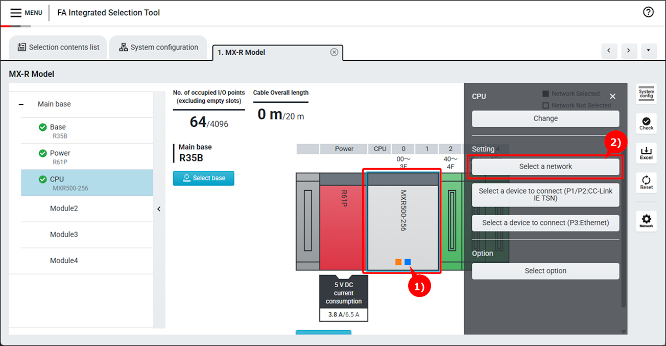
1)Click a module to be connected to a network.
2)Click "Select a network" button.
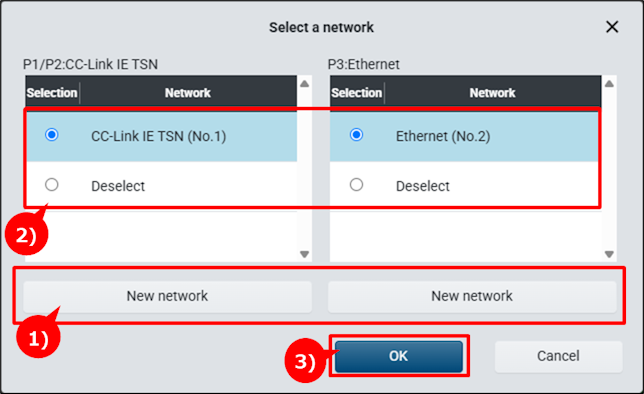
1)Click "New network" button to connect to a new network.
When topology selection is necessary, the topology selection screen will be displayed.
2)Select a network to connect.
3)Click "OK" button.
4)The square on the module changes to solid.
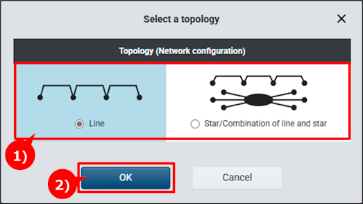
1)Select a network topology.
2)Click "OK" button.
3)A network is configured with the selected topology.
Step 6:Error check
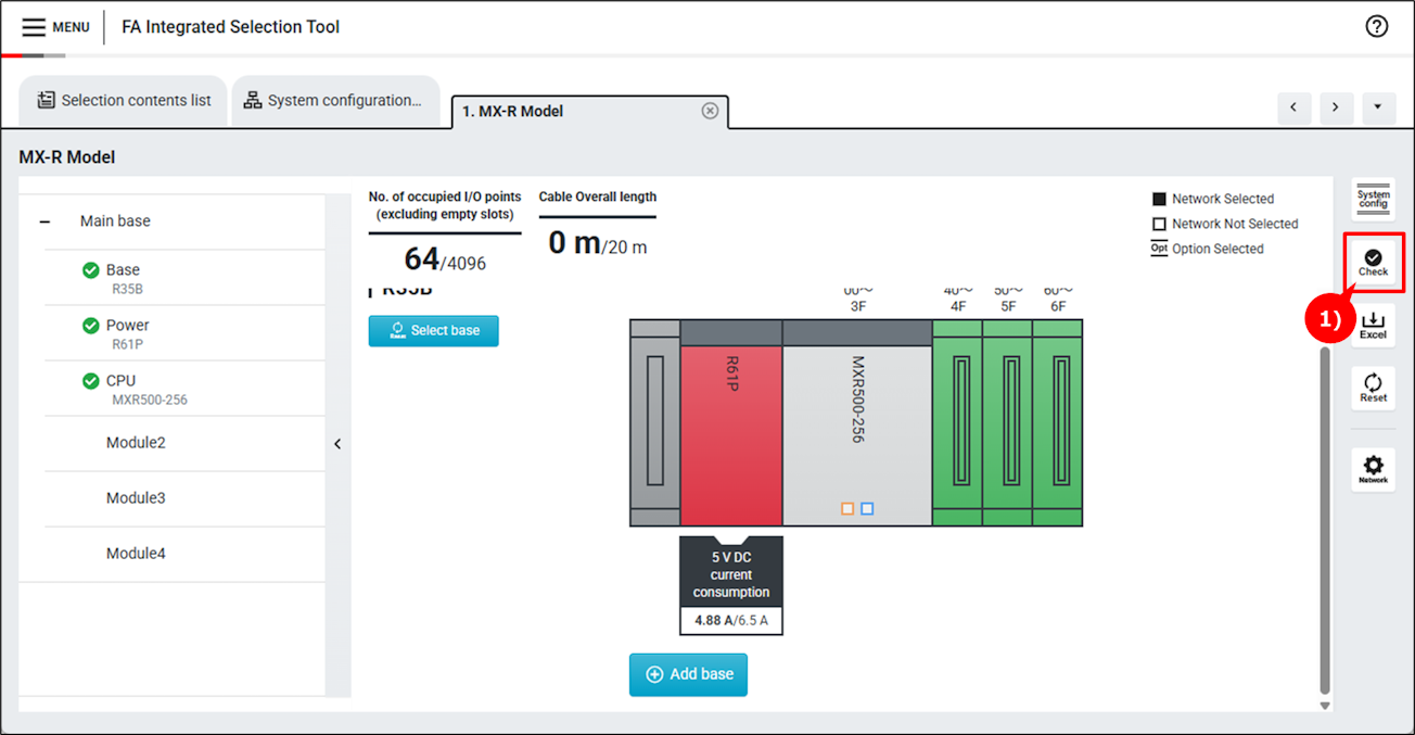
1)Click "Error check" button.
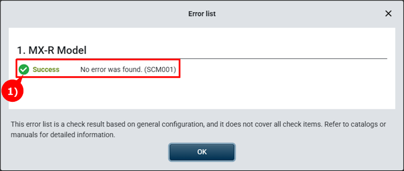
1)If no error nor warning is found, "Success" will appear.
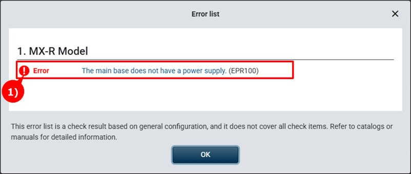
1)If an error or warning is found, details will be displayed.
Step 7:Module network connection settings
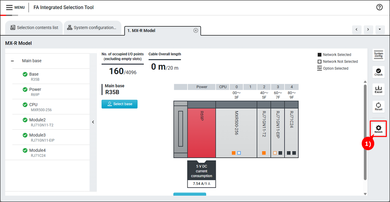
1)Click "Module network connection settings" button.
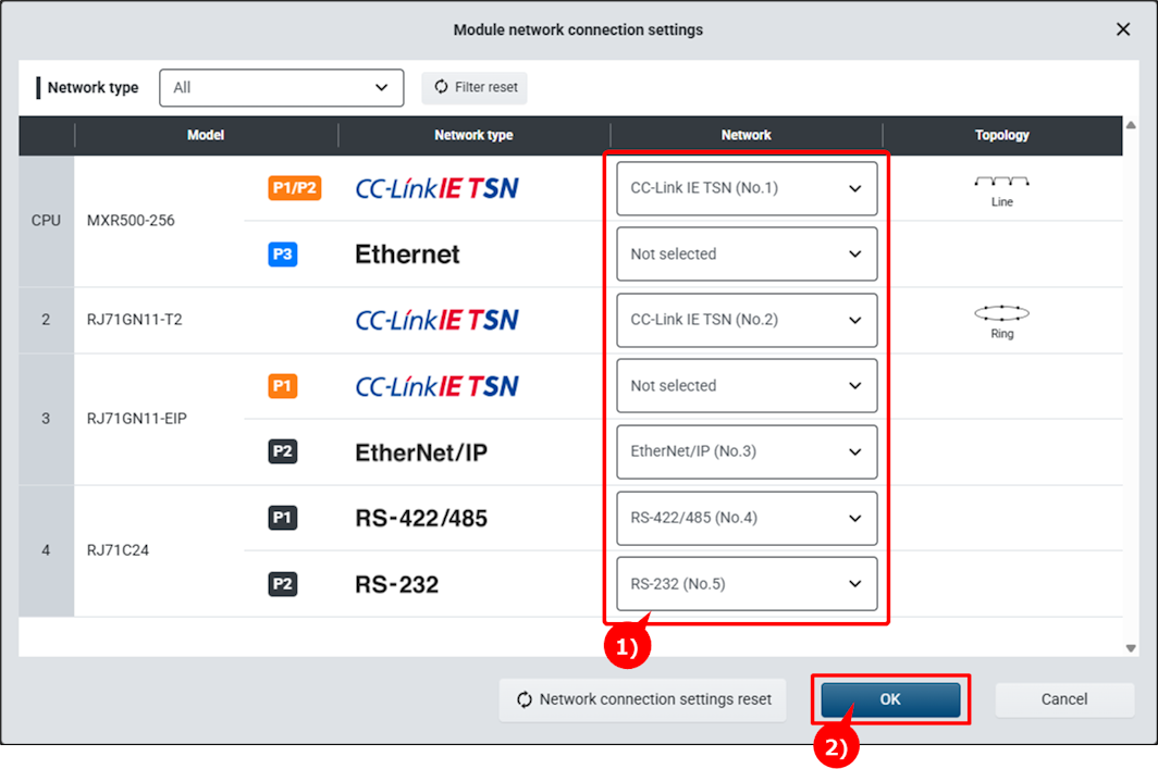
1)Select a network to connect.
2)Click "OK" button.
3)Your unit will connect to the selected network and the square on the module changes to solid.